
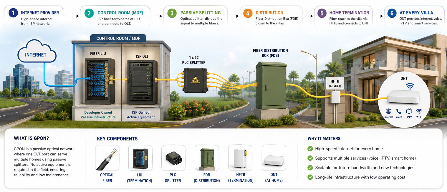
One Fiber Infrastructure. Multiple Homes. Multiple Possibilities.
For developers, builders and facility owners, the right FTTH architecture is not simply about choosing an OLT or ONT.
It is about building a communications infrastructure that remains useful as technology, bandwidth requirements, service providers and community applications evolve.
The Question Every Developer Should Ask
When developing a gated community, villa project, apartment complex or township, connectivity is often considered only towards the later stages of the project—when individual homes need Internet and ISPs begin approaching the property. But by then, an important opportunity may already have been lost.
The most valuable part of a community’s communication infrastructure is what gets built into the property itself. Underground ducts, fiber backbone, distribution points, fiber termination facilities and a properly planned communication room are long-life assets of the development. Once roads, driveways, landscaping and homes are completed, adding or replacing this infrastructure can become expensive, disruptive and sometimes impractical.
This is why communication infrastructure should be planned alongside the property’s other essential infrastructure—not as an afterthought once the project is ready for occupancy. The developer does not need to predict exactly which ISP, technology or bandwidth requirement will exist several years from now. Instead, the objective should be to create a robust, scalable and ISP-flexible physical infrastructure that can accommodate changing requirements over time. Build the common infrastructure once .Let ISPs, technologies and services evolve over it.
A properly planned GPON/FTTH infrastructure provides this foundation—connecting the Control Room to the distribution network and ultimately to every villa, while creating the potential to support not just Internet connectivity, but also IP surveillance, intercom, access control, Wi-Fi and future smart-community applications.
1. What Is GPON?
GPON — Gigabit Passive Optical Network — is a fiber-access architecture in which an Optical Line Terminal (OLT) communicates with multiple Optical Network Terminals (ONTs/ONUs) through an optical distribution network.
The distribution network can include optical fiber and passive optical components such as splitters, creating a point-to-multipoint architecture between the OLT and subscriber endpoints.
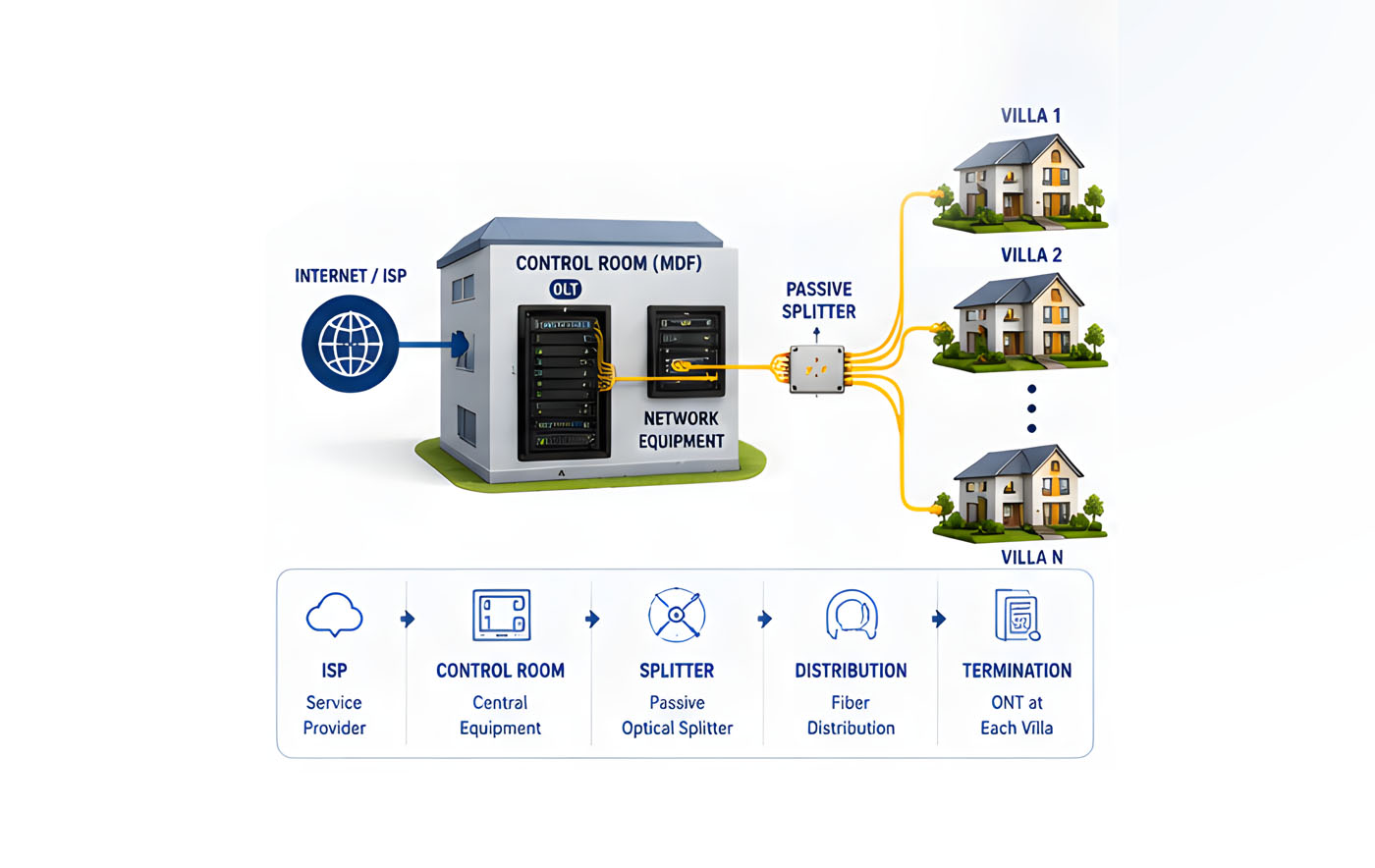
In simple terms, One central optical access system → passive fiber infrastructure → multiple homes. A typical GPON/FTTH deployment can include:
- OLT
- Optical fiber backbone
- Passive optical splitters
- Fiber Distribution Boxes
- Fiber LIUs
- Home Fiber Termination Boxes
- ONTs
- Network switches
- Power and UPS
- Fiber testing and documentation
The important point is that GPON is only one part of the overall infrastructure and the quality and future usefulness of the project depend equally on how the underlying fiber infrastructure is designed.
2. The Journey: Think of the community’s fiber network much like a road network.
The ISP brings Internet connectivity to the community. The Control Room / MDF acts as the central hub, and the fiber backbone acts as the highway connecting that hub to different parts of the development.
From the backbone, connectivity is progressively distributed to individual villas, where the ONT provides the final connection to the resident’s network.
The journey is therefore:
ISP Connectivity
↓
Community Control Room / MDF(Central Hub)
↓
Fiber Backbone(Community-wide Connectivity Highway)
↓
Distribution Points(Connectivity reaches each zone/cluster)
↓
Villa Fiber(Dedicated connection to each home)
↓
ONT(Optical signal converted to the resident’s network connection)
↓
Villa / Home Network
3. What Goes Underground?
The most important part of a community’s communication infrastructure is often the part residents never see.
Before roads, driveways and landscaping are completed, the underground pathways for the community’s fiber network need to be planned and protected. These pathways form the foundation through which connectivity can reach every villa today—and support future expansion tomorrow.
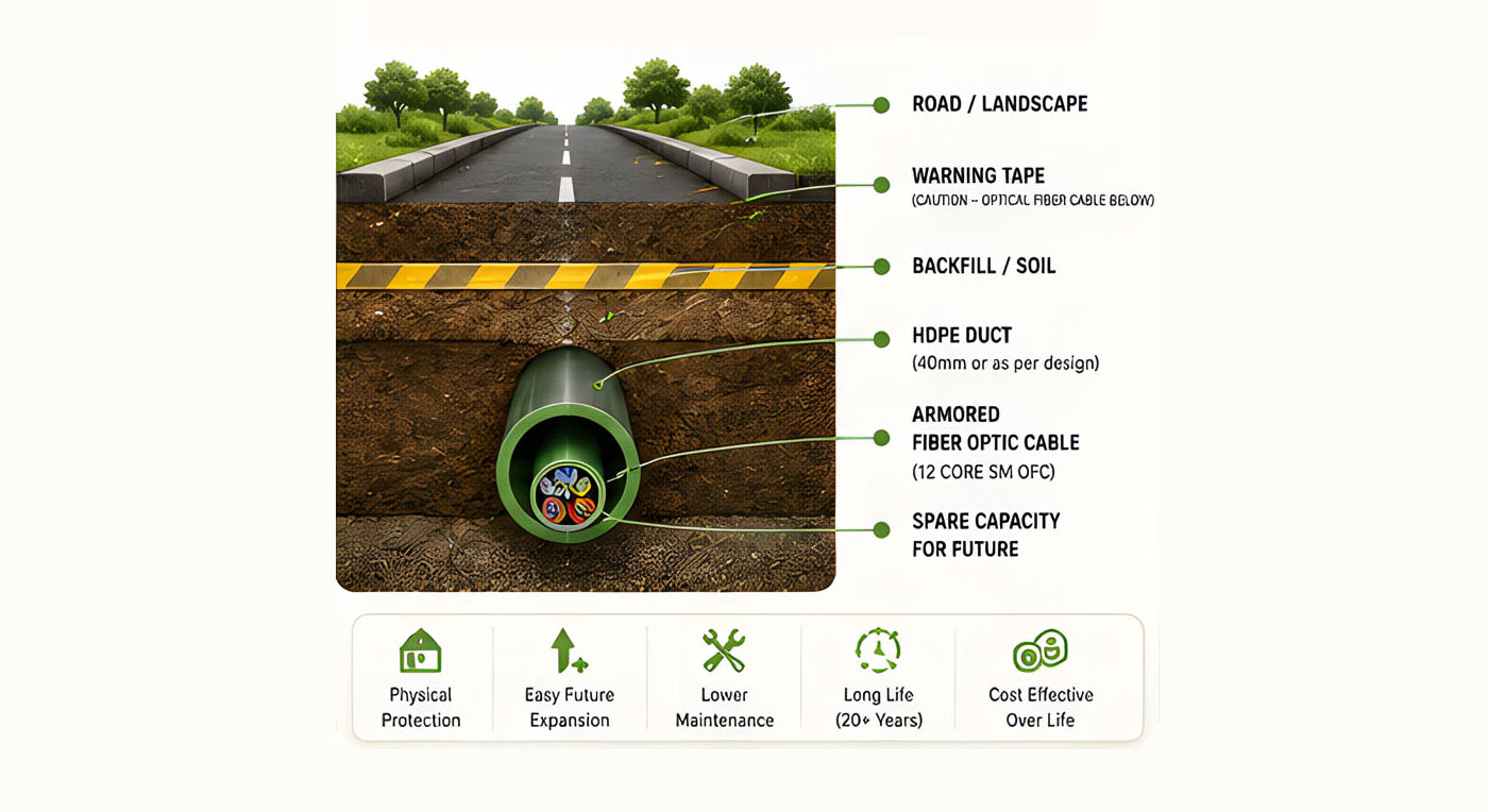
Once the development is completed, the fiber infrastructure is largely hidden beneath the property, running through roads, driveways, landscaped areas, common spaces and pathways.
A properly planned underground fiber route typically comprises:
- HDPE telecom duct — providing a protected pathway for the fiber
- Armored single-mode optical fiber — carrying the communication services
- Caution / warning tape — providing a visible indication of the underground fiber route
- Chambers / handholes, wherever required, to facilitate access and maintenance
- Route markers and identification — helping locate the infrastructure in the future
- Properly documented routes — essential for maintenance, expansion and future civil work
The HDPE duct is particularly important because it protects the optical cable from the mechanical and environmental stresses associated with underground installation. It also provides a defined pathway for future maintenance or cable replacement.
The duct size should be determined based on the actual fiber cable diameter, installation method, route conditions and any justified future capacity requirements. It should be engineered for the project rather than selected simply on the basis of a generic standard.
Why plan this before handover?
Once a community is occupied, carrying out civil work becomes significantly more difficult.
Roads have been completed.
Driveways are in use.
Landscaping has been established.
Residents are living in their homes.
Adding new fiber later may therefore mean reopening roads, disturbing landscaping and undertaking additional civil work—all of which can be considerably more disruptive and expensive.
The best time to build and protect the communication pathways is while the property is being developed—not after it is occupied.
Build the pathway today. Keep the network ready for tomorrow.
4. Why Consider 12-Core Fiber When the Actual Requirement Is 4-Core?
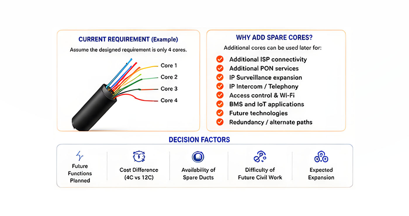
- Future service requirements
- Cost difference between 4-, 6- and 12-core fiber
- Availability of spare duct capacity
- Ease of future fiber installation
- Likely cost and disruption of future civil work
Therefore, in any project, if 4 cores meet the current requirement, considering at least 12-core fiber—provided the incremental cost is reasonable—can be a prudent way to build spare capacity for future expansion and avoid potentially expensive and disruptive civil work later.
5. Inside the Control Room — The Heart of the Network
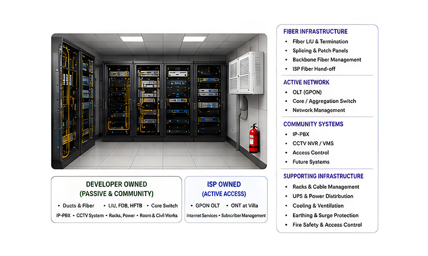
The Control Room / MDF is the central point from which the community’s communication infrastructure is organized.
It may contain or provide space for:
Fiber Infrastructure
- Fiber LIUs
- Fiber termination
- Splicing
- ISP fiber handoffs
- Backbone fiber management
Active Network Infrastructure
- OLTs, where applicable
- Core / Aggregation Switch
- Distribution uplinks
- Network management
Community Systems
- IP-PBX
- CCTV NVR/VMS
- Access Control
- Future smart-community systems
Supporting Infrastructure
- UPS
- Power distribution
- Earthing
- Cooling
- Rack management
- Physical security
A good Control Room should not only accommodate today’s equipment. It should provide reasonable space and infrastructure for tomorrow’s requirements.
6. LIU, Splitter, FDB and HFTB — What Do They Actually Do?
These components are frequently confused because they all form part of the optical network.
However, each has a different purpose.
LIU — Fiber Termination & Patching
A Light Interface Unit (LIU) is essentially the fiber termination and patching point.
It provides:
- Fiber termination
- Connector interfaces
- Splice management
- Patch-cord connectivity
- Fiber identification
- Fiber management
Think of an LIU as:
The patch panel of the optical network.
An LIU does not split the optical signal.
PLC Splitter — One Optical Signal to Multiple Outputs
A PLC splitter is a passive optical device used to divide an optical signal into multiple outputs.
For example:
1 × 32 PLC Splitter
1 optical input → multiple optical outputs
This allows a PON architecture to distribute connectivity to multiple endpoints.
The actual number of usable subscribers depends on the:
- Optical budget
- Split ratio
- OLT capability
- Network design
- ISP configuration
FDB — Fiber Distribution Box
A Fiber Distribution Box is generally installed closer to the villas.
It provides a protected location for:
- Fiber splicing
- Fiber distribution
- Drop-fiber management
- Connector termination
- Cable organization
HFTB — Home Fiber Termination Box
The HFTB provides the final passive fiber termination point at or near the villa.
The typical path is:
Backbone Fiber → FDB → Drop Fiber → HFTB → ONT
7. How One Fiber Reaches Multiple Villas
A major strength of a PON architecture is its point-to-multipoint design. A single PON interface can serve multiple endpoints through passive optical splitting, subject to the optical budget and network design.
Instead of requiring a dedicated active optical connection from the Control Room to every villa, the optical signal can be passively split and distributed across multiple homes.
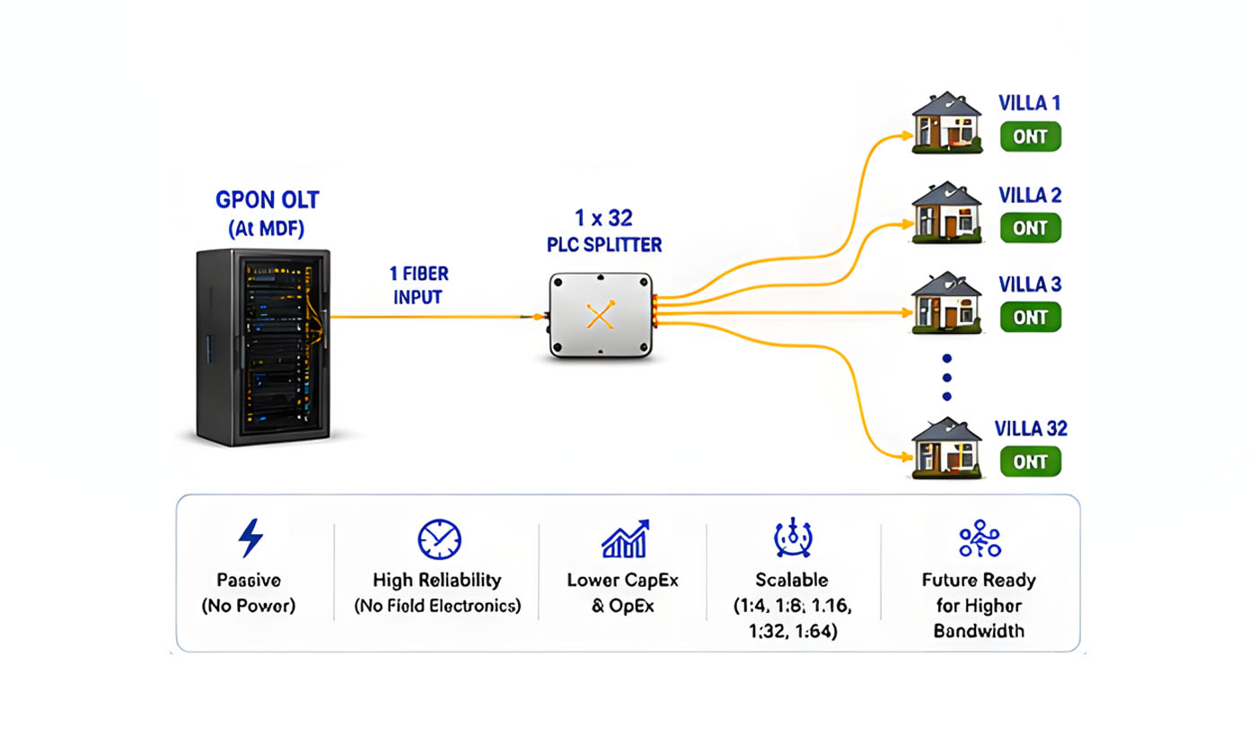
For example, a 1×32 optical splitter can take one optical input and distribute it across multiple output fibers, subject to the OLT capability, optical budget and overall network design.
Why is this particularly useful for a gated community?
The splitter is passive—it does not require:
- Electrical power
- Active electronics
- Network configuration
- A powered switch at the splitter location
This means the optical distribution points can be located closer to villa clusters without having to provide power and active network equipment at every location. The result is a simpler field infrastructure with fewer powered devices to maintain, while allowing the central Control Room to serve a large number of villas through the community’s fiber backbone.
In simple terms:
One central optical network can fan out to multiple villas through passive splitters—reducing the need for powered equipment across the community.
This is one of the key reasons PON architecture is well suited to large residential developments, gated communities and villa projects, where homes may be spread across a large physical area.
The important design consideration
Passive splitting does not mean that the network can be split indefinitely. The split ratio, fiber distance, connector/splice losses and optical power budget must all be considered when determining how many villas can be served from each PON interface.
The objective is not simply to maximize the number of villas per PON, but to achieve the right balance between coverage, optical performance, scalability and future expansion.
8. One Fiber Infrastructure — Multiple Community Services
Why build separate connectivity infrastructure for every application when one well-planned fiber backbone can provide the foundation for the entire community?
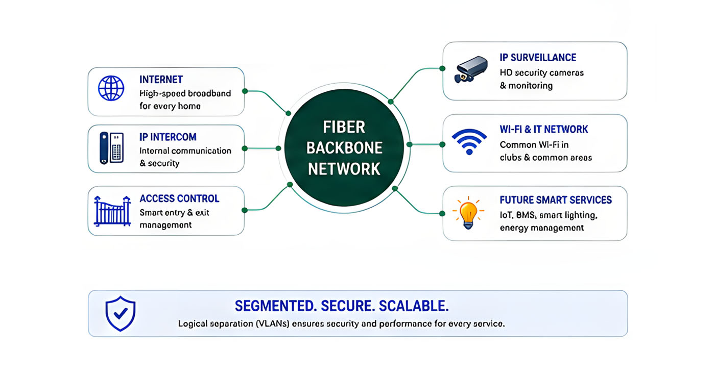
A well-planned fiber and network infrastructure can provide the common connectivity foundation for much more than residential Internet.
From the Control Room / MDF, the community fiber backbone can support:
- Residential Internet — connectivity to individual villas.
- IP Surveillance — cameras, PoE switching and centralized recording.
- IP Intercom & Telephony — communication between villas, security gates, clubhouse and administration.
- Access Control — gates, readers and associated security systems.
- Community Wi-Fi — clubhouses, amenities and common areas.
- Future Smart-Community Services — BMS, IoT, smart lighting, energy monitoring, visitor management and other IP-based applications.
The key principle
The fiber is the underlying infrastructure. The applications use that infrastructure. These services do not necessarily need to share one common network. VLANs, routing, ACLs and other security controls can be used to logically separate services and protect the network.
Build one robust infrastructure. Create multiple services over it.
9. IP Surveillance and IP Intercom Are Not the Same as GPON
GPON provides the optical access infrastructure, while IP Surveillance and IP Intercom are applications that use the underlying fiber and IP network to connect distributed endpoints back to the Control Room.
Although they serve very different purposes, both can follow the same fundamental principle:
Centralized Control Room / MDF → Community Network → Distributed Endpoints
The two applications can then be designed and managed independently according to their respective requirements.
IP Surveillance — From the Control Room to the Cameras
The surveillance network starts at the Control Room / MDF, where the NVR/VMS and core network infrastructure are located.
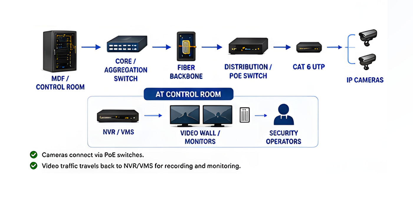
Connectivity is then extended across the community through the fiber backbone to the distribution points and PoE switches, with the final connection to each camera typically provided over Cat 6.
CONTROL ROOM / MDF
↓
Core / Aggregation Switch
↓
Fiber Backbone
↓
Distribution / PoE Switch
↓
Cat 6 UTP
↓
IP Cameras
The cameras are distributed throughout the property, while video recording, monitoring and management remain centralized in the Control Room.
IP Intercom — Control Room to Villa / Endpoint
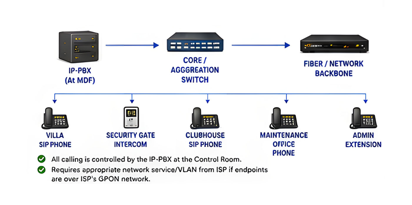
↓
IP-PBX
↓
Core / Aggregation Switch
↓
Community Fiber / Network
↓
Distribution Network
↓
Villa / Security Gate / Clubhouse / Administration
↓
SIP Phone / IP Intercom Endpoint
10. What Happens When Multiple ISPs Are Involved?
The developer may build the basic communication infrastructure and ecosystem while keeping the project flexible enough to accommodate the GPON architecture of the ISP eventually selected.
The developer does not necessarily need to own the ISP’s active equipment. Instead, the infrastructure can provide the necessary:
- Control Room / MDF space
- Rack, power and cooling provisions
- Fiber LIUs and termination
- HDPE ducts and fiber pathways
- Distribution points / FDBs
- Villa-level fiber termination
- Spare capacity for future expansion
This approach allows the selected ISP to deploy its own GPON Gateway/OLT, ONTs and associated equipment within the infrastructure already provisioned by the developer, with minimal modification to the overall network.
Why plan this upfront?
If an ISP introduces its own GPON architecture after the community is completed, accommodating it could require additional fiber, ducts, termination points and equipment space—potentially leading to civil work, road or landscape disruption, resident inconvenience and additional cost.
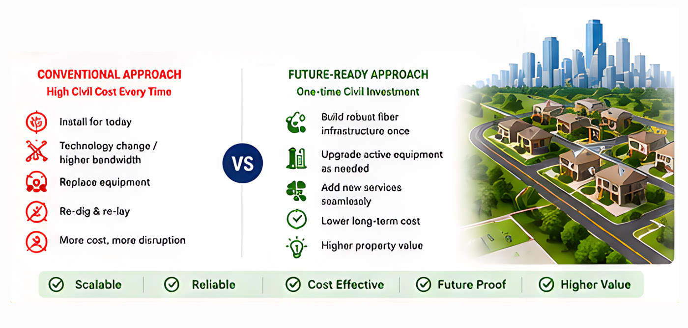
The objective of the developer should therefore be to build the ecosystem once & let the ISP bring its technology into it—without having to rework the community later. This becomes particularly important in a multi-ISP environment, where different providers may have different GPON deployment and infrastructure requirements.
We Hope This Gives You a Clearer Picture
We hope this guide has given you a clearer understanding of how to approach GPON/FTTH infrastructure for a gated community or similar development—from planning the fiber backbone and underground pathways to accommodating ISPs, villas, IP Surveillance, Intercom and future communication requirements.
More importantly, we hope it helps you ask the right questions before the infrastructure is built, so that today’s decisions do not become tomorrow’s costly rework.
Whether you follow this approach or choose a different one, the objective should remain the same: build a robust, scalable communication infrastructure that is ready for today’s requirements and adaptable to tomorrow’s possibilities.
Planning a New Community or FTTH Deployment?
You don’t have to figure it out only after the roads are laid, the villas are occupied and the ISP arrives with its own requirements.